
Continuous Torque Is Primarily a Thermal Problem
A compact motor can achieve its peak torque target yet fail to sustain the required output over time. The limiting factor is usually not magnetic capability, but temperature rise.
Continuous torque is defined by the balance between heat generation and heat removal. As operating current increases, electrical losses generate heat in the windings and magnetic core. If that heat cannot be removed fast enough, winding temperatures can exceed the design limit, forcing a reduction in current and therefore torque. Continuous torque is as much a thermal rating as an electromagnetic one.
Peak Torque and Continuous Torque Measure Different Capabilities
Peak torque represents the maximum torque available for a limited period. Continuous torque represents the torque that can be sustained at thermal equilibrium under specified operating conditions.
Consider a robotic joint. High torque may be needed only during acceleration, but holding position can require sustained current with little mechanical output. Although the peak demand is brief, the holding condition may determine the motor’s thermal limit. The same distinction matters in enclosed packages, elevated ambient temperatures, and applications with repeated duty cycles.
A continuous torque rating is therefore meaningful only alongside operating speed, duty cycle, ambient temperature, mounting arrangement, and cooling conditions.
Why Windings Usually Set the Limit
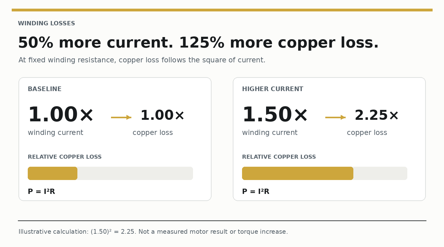
In many compact motors, winding temperature is the primary constraint. Torque production requires current, and current generates copper losses according to P = I²R.
Because resistive losses increase with the square of current, a modest increase in torque-producing current can produce a much larger increase in heating. Copper resistance also rises with temperature, adding losses as the winding approaches its thermal limit.
For many applications, maximum continuous torque is reached when the allowable winding temperature is reached - not when the electromagnetic circuit runs out of torque-producing capability.
Core Losses Become More Important at Speed
Copper loss is only part of the thermal budget. Hysteresis and eddy-current losses in the magnetic core can become increasingly significant as electrical frequency increases. Their magnitude depends on material properties, flux density, frequency, and the magnetic circuit.
A motor designed for low-speed holding may consequently have a different loss distribution from one operating in a high-speed pump, fan, or traction application. Optimizing the copper alone does not establish continuous performance across the speed range.
Heat Removal Is Often the Real Constraint
Generating less heat is only half the problem. The other half is getting it out of the motor.
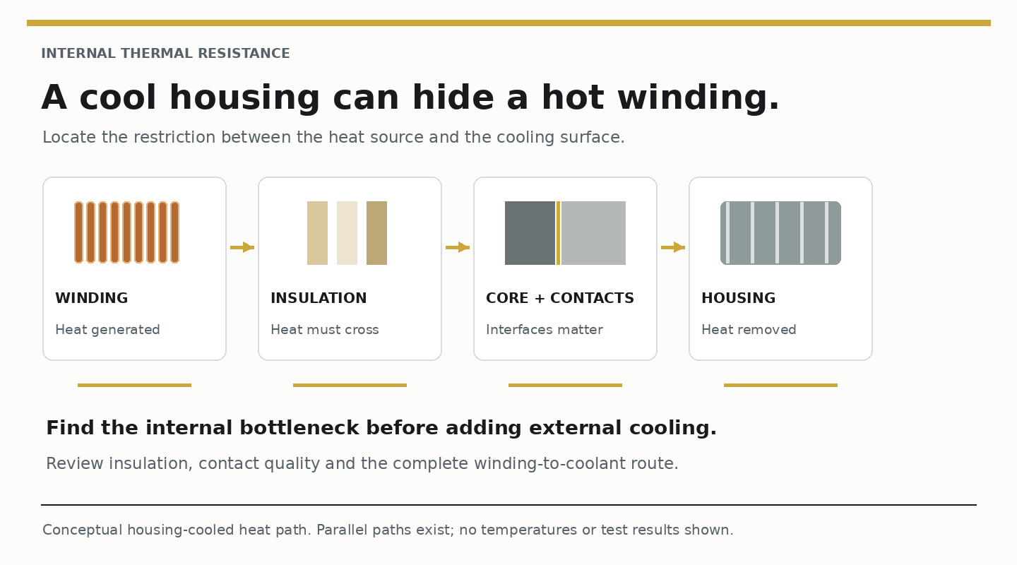
In a housing-cooled design, heat from the winding typically passes through insulation, slot materials, the stator core, mechanical interfaces, and the housing before reaching a cooling jacket or surrounding air. Each interface contributes thermal resistance.
The housing may therefore remain relatively cool while winding temperature approaches its limit. Increasing external cooling capacity may offer little benefit when the largest temperature drop occurs between the winding and the housing. Thermal-path analysis should establish where that drop occurs before more cooling hardware is added.
Continuous Torque Depends on Motor Architecture
Once the sources of loss and the heat-transfer path are understood, motor topology becomes an engineering variable rather than merely a packaging choice.
Can winding length and resistance be reduced? Can copper fill be improved? Can cooling surfaces be brought closer to the windings? Can thermal interfaces be simplified - or core losses reduced through a different magnetic circuit?
These questions move the design discussion beyond increasing the size of the cooling system. They also explain why a change in motor architecture can be worth evaluating.
How Soft Magnetic Composites Expand Design Options
Soft Magnetic Composites (SMCs) allow magnetic components to be formed into three-dimensional geometries that are difficult to produce with conventional laminated steel. Electrically insulated iron particles enable greater freedom in magnetic-circuit design, coil placement, cooling-path integration, and manufacturing approach.
The opportunity is not material substitution for its own sake. It is the ability to evaluate motor architectures that might shorten the heat path, change the winding arrangement, or reduce losses.
Any continuous-torque improvement must still be demonstrated at the motor level. The finished component's magnetic behavior, the winding and cooling arrangements, and the operating point determine whether the proposed design delivers an advantage.
Yokeless Axial-Flux Machines Illustrate the Principle
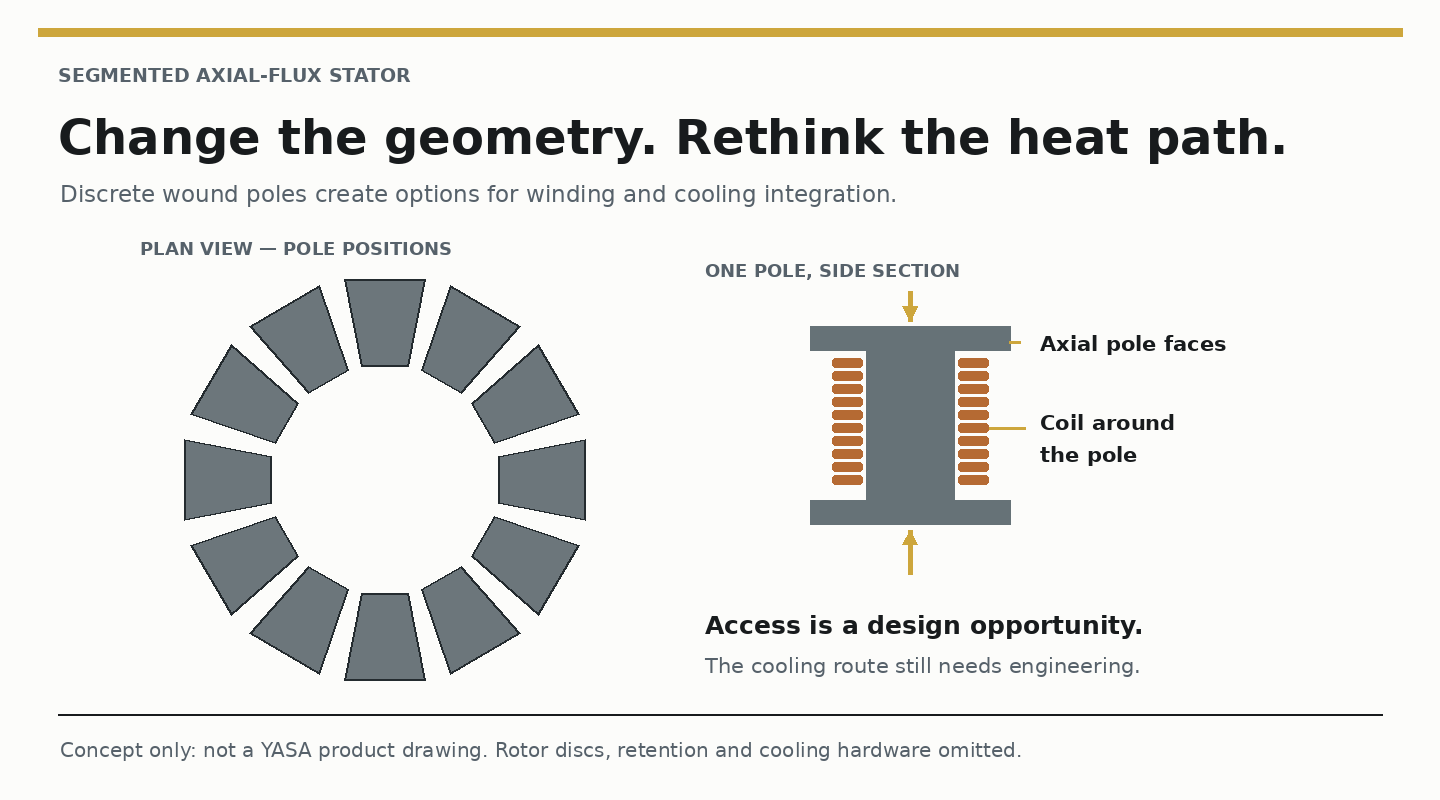
Yokeless, segmented axial-flux machines show how topology, material selection, and cooling can be considered together. Eliminating the circumferential stator yoke and using individual pole segments can shorten winding length, improve access during manufacturing, and create additional opportunities to reach the windings with cooling.
The possible thermal benefit comes from the actual copper path and heat-removal arrangement - not simply from using an axial-flux topology. A poorly cooled axial-flux motor can still be limited by winding temperature.
Transverse-Flux Machines Can Shift the System-Level Tradeoff
In low-speed, high-torque applications, the design opportunity may extend beyond the motor. A transverse-flux architecture may support a direct-drive arrangement that reduces or eliminates the need for a gearbox.
That comparison must be made at system level. Motor efficiency and thermal performance matter, but so do gearbox losses, packaging, total weight, and maintenance. The relevant question is whether the complete drive system sustains the required output more effectively - not whether one motor configuration produces a higher isolated torque number.
Material Selection Must Support the Architecture
Changing the magnetic circuit changes the requirements of the core material. SMC performance can be tailored by judicious application of material and processing methods.
Because magnetic losses are sensitive to these variables, characterization should reflect the material and finished component being proposed. Catalog data alone cannot establish the thermal performance of a new motor architecture.
Validate Continuous Torque Under Real Operating Conditions
The final comparison must reproduce representative duty cycles, speed range, load profile, mounting arrangement, ambient conditions, and cooling configuration. Temperature measurements should consider the winding, not just the housing, because internal thermal resistance may determine the actual limit.
Peak output is an incomplete measure. The useful result is torque that remains available after the motor reaches thermal equilibrium.
Conclusion
Continuous torque is governed by thermal management. Copper losses, core losses, thermal resistance, cooling strategy, and motor architecture all determine whether a motor can sustain its required output after warm-up.
For engineers evaluating Soft Magnetic Composites, the key question is not whether the material enables a novel topology. The critical question is whether that topology reduces losses, improves heat extraction, or accomplishes both within the constraints of the intended application.
Ultimately, continuous torque is earned through the combined performance of the winding, magnetic circuit, thermal path, and cooling system rather than any single component in isolation.
Frequently Asked Questions About Continuous Torque
What is continuous torque in an electric motor?
Continuous torque is the torque an electric motor can sustain at thermal equilibrium under specified operating conditions. A meaningful rating includes motor speed, ambient temperature, mounting, and cooling conditions.
What is the difference between peak torque and continuous torque?
Peak torque is the maximum torque a motor can deliver for a limited time. Continuous torque is the output it can sustain once temperatures stabilize. A robotic joint can draw current and heat its windings while holding position, even when its shaft is stationary.
Why do compact electric motors lose available torque as they heat up?
The motor may need to operate at lower current to keep the windings within their allowable temperature. Winding copper loss increases with the square of current (P = I²R), and hotter copper has higher electrical resistance. Both effects consume part of the motor’s thermal budget.
Why can a motor housing feel cool while the windings run hot?
Insulation, slot materials, the stator core, and mechanical interfaces can resist heat flow between the windings and the housing. If most of the temperature drop occurs inside the motor, additional external cooling may produce only a small reduction in winding temperature.
Can soft magnetic composites improve continuous torque?
Soft magnetic composites can enable three-dimensional magnetic components that give designers more options for coil placement and cooling. Continuous torque can improve if the resulting motor reduces losses or removes heat more effectively. Compare the finished designs under the same operating and cooling conditions to verify the effect.
How should engineers validate a motor’s continuous torque rating?
Test the finished motor at representative speeds, loads, and duty cycles with the intended mounting, ambient temperature, and cooling. Monitor winding temperature as well as housing temperature, and confirm that the motor sustains the required torque after temperatures stabilize.