
The most expensive manufacturing problems are often designed into a component long before anyone recognizes them. An SMC stator tooth may meet every magnetic target yet prove difficult to press, vulnerable during handling, or unnecessarily complex to assemble. What appears to be a minor geometric detail in the CAD model can become a source of variation, increased cost, and production risk on the factory floor.
That is why manufacturability must be considered alongside performance from the earliest stages of design. The geometric shape of the component and how it affects the forming process matter. Section thickness, winding interfaces, tolerances, and assembly loads all influence whether a component can be produced consistently, economically, and at scale. The objective is not simply to achieve the required magnetic performance, but to achieve it with a design that can be manufactured reliably throughout its production life.
What Makes SMC Component Design Different from Laminations?
Soft Magnetic Composites (SMC) are produced by compacting electrically insulated magnetic powder particles into a net-shape component and then thermally processing the material under controlled conditions. Unlike laminated electrical steels, SMCs support three-dimensional magnetic flux paths, giving engineers greater freedom to create magnetic circuits that would be difficult or impractical using stacked laminations.
This design freedom is particularly valuable in axial-flux machines, transverse-flux machines, segmented stators, and other applications where complex magnetic pathways can deliver performance benefits. However, it also introduces a different set of engineering tradeoffs. A geometry that appears straightforward in a machined metal component may present entirely different manufacturing challenges when formed from compacted powder.
Material selection is equally important. Magnetic performance depends not only on the chosen SMC grade, but also on achieved density, processing parameters, operating frequency, and flux density. Core-loss data and B-H curves should be evaluated in the context of the intended application and manufacturing route. The material grade is only one element of the design. Success ultimately depends on the performance of the complete magnetic circuit.
Define SMC Component Requirements Before Designing Geometry
Before modifying geometry or assigning tolerances, define exactly what the component must accomplish within the assembly. Which surfaces establish the air gap? Where is the coil positioned? How is the core retained? Which regions carry the highest magnetic loading, and how will heat be removed from the system?
Answering these questions early helps distinguish truly critical features from details that can be optimized for manufacturing. A productive design review should consider operating conditions, cooling requirements, assembly interfaces, and expected production volumes alongside the magnetic objectives.
This approach often reveals opportunities that would otherwise be overlooked. A tooth tip may have very little geometric flexibility because of its magnetic function, while a mounting face or locating feature may offer significant freedom for tooling, handling, or assembly improvements. Establishing those priorities early creates more options later in the development process.
How Component Geometry Affects SMC Manufacturability
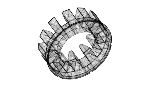
Once the component's functional requirements are understood, the next step is to determine how it will be manufactured. Every SMC component must allow powder to fill the tooling effectively, compact uniformly, and be ejected without unacceptable damage.
Features such as cross-holes, undercuts, deep cavities, or abrupt section changes should therefore be reviewed early in development. Their presence does not necessarily eliminate a design from consideration, but it should prompt discussion about feature orientation, tooling strategies, secondary operations, or potential design modifications.
Part size must also be evaluated in context. Feasibility depends on more than the component's largest dimension. Projected area perpendicular to the pressing axis, compaction pressure requirements, tooling design, press capacity, and ejection forces all contribute to the manufacturing window. For this reason, no universal maximum size exists for SMC components.
What Determines Minimum Wall Thickness in SMC Components?
As geometry evolves, engineers must balance the amount of iron needed to support flux loading, along with strength and weight considerations to fully optimize the motor design. Engineers naturally seek to maximize available winding space and reduce overall component size, but reducing section thickness can introduce manufacturing and handling challenges.
Thin sections must survive compaction, ejection, inspection, handling, winding, assembly, transportation, and installation. A section that appears acceptable in the CAD model may create unnecessary risk if it cannot endure those manufacturing steps consistently.
For that reason, published thickness guidelines should be treated as starting points rather than design limits. Final dimensions should always be reviewed with the manufacturing team before release.
Why Density Distribution Matters in SMC Core Design
A component’s average density does not tell the whole story. Powder fill, pressing direction, and friction within the tooling can produce different local compaction conditions. For an SMC stator core, the manufacturing review should consider whether the material data used in the motor model represents the component and process being proposed.
Review narrow regions and transitions between sections together with the tooling strategy. If the intended density cannot be achieved consistently, changing the component orientation or dividing the geometry into segments may offer a more practical production route. Resolve these decisions before finalizing the electromagnetic model and tooling design.
Designing SMC Components for Winding and Assembly
SMC design does not end with the magnetic core. The component must integrate successfully with coils, insulation systems, retention features, and assembly processes.
Many manufacturing issues originate at these interfaces. Sharp edges may complicate winding operations. Limited access may increase assembly complexity or create opportunities for damage that are not apparent in electromagnetic simulations.
Segmented architectures often illustrate both the advantages and challenges of this relationship. Individual tooth segments can improve winding access and simplify coil placement, but those gains must be balanced against assembly considerations such as segment retention, bond quality, mechanical support, tolerance accumulation, and unintended magnetic gaps.
Plan how the core will be supported during coil placement and final assembly. Identify the surfaces that can accept clamping or retention loads, protect the winding insulation, and check that the assembly sequence remains practical at the intended production volume. A useful design review follows the component through the complete assembly process.
Which SMC Component Tolerances Matter Most?
Tolerance strategy should be driven by function, not by a desire to make every dimension as precise as possible.
Some features directly affect performance and require strict control. Air-gap surfaces, coil interfaces, locating features, and assembly datums often fall into this category. Other dimensions may contribute little to system performance and can often tolerate greater variation without consequence.
The objective is to identify the dimensions that truly matter and define a measurement strategy around them. This includes establishing datums, selecting inspection methods, and determining at what stage each feature should be verified.
Assembly effects must also be considered. A dimension measured on an individual segment may not accurately represent the geometry of the completed stator. Tolerance-stack analyses, joining processes, and finishing operations should therefore be incorporated into the review.
When this process is completed effectively, the drawing becomes a communication tool rather than a constraint. Critical interfaces remain protected while manufacturing teams retain the flexibility needed to produce parts efficiently.
Can SMC Components Be Machined?
Yes.
Machining can be a practical option for suitable SMC materials and prototype objectives, but its usefulness depends on the question being asked. Material grade, fixturing strategy, feature geometry, and machining method all influence the outcome. It should not be assumed that every SMC grade can be machined successfully, or that a machined prototype will accurately represent the properties of a compacted production component.
Prototype strategy should therefore be aligned with project objectives. A machined part may provide valuable insight into packaging constraints, winding access, or assembly sequences while the design is still evolving. However, when the goal is to validate magnetic performance or understand the effects of compaction, representative materials and manufacturing processes become increasingly important.
Define acceptance criteria before choosing the prototype route. A packaging trial should establish fit and assembly access; a magnetic-performance trial should use an agreed material condition and test method. Documenting that distinction helps the team decide which results can support a production design decision.
SMC Design Checklist: What to Review Before Tooling Release
Before committing to production tooling, bring magnetic performance, manufacturability, and assembly requirements together in a single review.

The checklist connects material selection and simulation assumptions to prototype validation. Complete the tooling review by agreeing on pressing direction, ejection, critical dimensions, winding and retention interfaces, inspection methods, and expected production volumes.
Frequently Asked Questions About SMC Component Design
Can SMC components have complex three-dimensional geometries?
Yes. Soft Magnetic Composites support three-dimensional magnetic flux paths and can be formed into geometries that may be difficult to achieve with conventional laminations. However, features such as undercuts, cross-holes, abrupt section changes, and thin walls must be evaluated against compaction, tooling, and ejection requirements.
When should an engineer involve an SMC manufacturer in the design process?
Ideally, before the component geometry and tolerances are finalized. Early manufacturing input can help identify tooling limitations, winding and assembly challenges, and potential production risks while the design still has flexibility.
Is there a standard minimum wall thickness for SMC motor components?
No single minimum applies to every SMC material and geometry. Wall thickness must support the magnetic design and survive forming, ejection, handling, winding, and assembly. Confirm the proposed sections with the component manufacturer before releasing the drawing.
What should an engineer provide for an SMC manufacturability review?
Provide the CAD model, critical dimensions and datums, operating frequency and flux-density range, material assumptions, winding and retention details, prototype objectives, and anticipated production volume. These inputs help the team evaluate the component and its production route together.
From Design Freedom to Manufacturing Reality
Soft Magnetic Composites have expanded what's possible in electric motor design, giving engineers greater freedom to develop complex geometries, three-dimensional magnetic circuits, and innovative stator architectures.
But that freedom brings an important responsibility: understanding how the decisions made during design influence what can ultimately be manufactured.
The greatest opportunities often emerge when magnetic performance and manufacturability are considered together. A subtle change in geometry, a more deliberate tolerance strategy, or a different approach to assembly can make the difference between a promising prototype and a component ready for repeatable production.
The real opportunity isn't simply designing a better magnetic component. It's developing one that delivers its intended performance consistently, efficiently, and at scale.
At Horizon Technology, we work alongside engineering teams to bridge that gap, bringing material expertise, component design, and powder metallurgy manufacturing experience into the development process. By addressing these relationships early, we can help preserve design intent while identifying practical opportunities to simplify manufacturing and reduce production risk.
Have an SMC Design You're Ready to Explore?
Whether you're developing a new stator architecture, refining an existing component, or evaluating the manufacturability of a complex geometry, we'd welcome the opportunity to review your design.
Share your geometry, performance requirements, and anticipated production volumes with our engineering team. Together, we can evaluate the critical design considerations and determine the most practical path toward prototyping and production.