Engineers designing for AC electrical applications are probably familiar with the concept of resistivity. Engineers consider resistivity in their electrical device design because they don’t want to generate heat and lose efficiency.
Below we’ll show how resistivity is a major design consideration for powder metallurgy AND laminations for electrical devices. We’ll also learn how powder metal actually surpasses motor lamination steel in electric motor efficiency.
Design Considerations for Powder Metallurgy: What Is Magnetic Resistivity?
Magnetic resistivity quantifies how strongly a material resists the flow of electric current. Unlike electrical resistance, which varies with the length, shape, and effects of cold work of the magnetic material; resistivity is independent of its shape or length.
Resistivity is expressed in units of ohm-meters; and is represented by the Greek letter rho (ρ). Materials with low resistivity will permit the easy passage of electrical current. Materials with high resistivity will resist the easy flow of electrical current.
Why Magnetic Resistivity Matters in Electrical Steel Laminations & Powder Metals
Why is resistivity important in AC magnetic devices? AC fields create eddy currents on the surface of the component; these currents resist the changing magnetic field.
Higher eddy currents result in greater losses because they are formed more readily in materials with low resistivity. Higher losses mean greater heat generation in the electrical device, resulting in reduced efficiency. Again, higher resistivity means an overall increase in efficiency.
Eddy current losses can be expressed as the following equation.
Pe =(Ke * Induction^2 * Freq^2 * thickness^2) / resistivity
- Pe -- eddy current loss
- Induction -- operation induction level of the magnetic device
- Freq -- operating frequency of the magnetic device
- Thickness -- thickness of the component or lamination
- Ke -- constant that depends on the material
Powder Metal Vs. Lamination Steel Properties
Let’s look at solving the resistivity problem from the standpoint of an engineer designing a motor for an electric car. What materials are used to make stators in motors? Typically, either powder metal or motor lamination steel. Both will take you places, but only one will fully maximize your motor’s potential.
Motor Lamination Materials
To reduce eddy losses, you must increase the resistivity or decrease the thickness of your lamination material. There is often a practical limit to how thin you can produce a steel lamination.
As a general rule, high resistivity begets high permeability. (This is a good thing.) However, alloying elements to the steel will increase resistivity but can also reduce magnetic permeability. Two alloying elements do raise both the permeability and resistivity: silicon and phosphorus.
Thus, for many lamination steels, silicon steels are the preferred alloying materials. Phosphorus is not typically used in steel laminations because it can cause hot shortness in steels, making it difficult to roll into thin sheets.
PM: Soft Magnetic Composite
Now let’s tackle how resistivity impacts the performance of a powder metal component -- specifically, one made from soft magnetic composite -- compared to a lamination for electrical devices. Soft magnetic composites (SMCs) are actually powder particles coated with a tiny electrically insulating layer that reduces the eddy losses you see in steel laminations.
This table shows the relative resistivity of motor lamination steel and SMC components. SMCs frequently demonstrate superior performance in higher operating frequencies. You might have what you think is a very good lamination steel, but at a certain frequency it starts to break down. Powder metal parts, meanwhile, excels at these certain levels.
Typical Resistivity of Steel Laminations and SMCs |
|
Material |
Resistivity (ohm-meter) |
Pure iron steel laminations |
~0.001 |
Silicon steel laminations |
~0.006 |
Soft magnetic composites |
>1.0 |
Our next chart shows what this means in terms of actual total loss performance of soft magnetic composite vs. lamination steel.
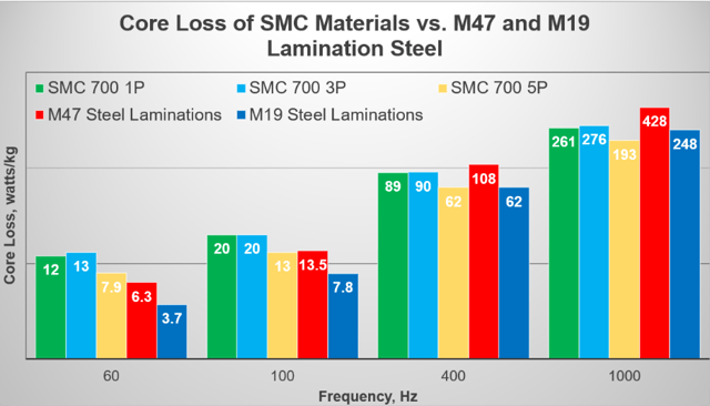
You can see soft magnetic composites compare very favorably to pure iron laminations (M47) at frequencies greater than 100 Hz. SMCs also perform better than silicon steel laminations at frequencies between 400 Hz and 1000 Hz. Thus, depending on your application, SMC can offer higher efficiency, and in turn lower cost of operation.
Reduce Your Assembly by 99%
A switch to soft magnetic composite can transform your component’s resistivity level from 90 to 9,000. Where this translates into tangible results is that you can manufacture a 10-piece assembly with SMCs instead of a 1,000-piece monstrosity.
This is truly one of the great advantages of powder metallurgy. In many AC applications, you don’t necessarily need to laminate materials anymore.
Is It Time to Switch?
Higher resistivity intrinsically gives you fewer efficiency losses in AC applications.
You may want to look into stacking PM parts instead of making thin sheets and stacking them. If your application is compatible with soft magnetic composite materials, you can stop worrying resistivity because it’s so inherently high in powder metal materials..
It’s time to change the rules of resistivity in magnetic part designs! Don’t let resistivity stand in the way of a good design!