Powder metallurgy (PM) is a highly unique and nuanced process, even down to the joining of parts. While welding is the obvious choice for many manufacturing processes, in PM there are not one, but two options that may better fit your application.
Sinder bonding and sinter brazing are two methods powder metallurgy manufacturers have at their disposal for joining parts.
However, the act of joining parts isn’t so cut and dry; there are many variables at play that determine the success of bonding and brazing. One such consideration is the coefficient of thermal expansion (COTE).
Keep reading to learn more about how sinter bonding and sinter brazing are impacted by COTE, and what PM manufacturers can do to improve the process.
Sinter Bonding & Brazing | Design Considerations for Powder Metallurgy
When traditionally sinter bonding two PM low-carbon steel components, the inner and outer components will have the same coefficient of thermal expansion (COTE). Think of a frozen nut on your car; one way to remove the nut is to heat it up so it expands and unthreads easier.
Sintering across the interface will depend on the initial gap and the relative growth and shrinkage of the inner and outer materials.
However, when two different materials are used as the inner and outer (such as stainless steel and an iron-phosphorus steel [FY-4500] or even a low-carbon steel) sinter bonding will be influenced by:
- The initial gap
- The relative COTE of the two materials
- The relative positioning of each material in the assembly
When determining the COTE of a powder metal material during sinter bonding and brazing, there are three primary complications:
- Density
- Temperature
- Dimensional change
Here’s the breakdown:
Density of PM Materials
Density is fairly easy to explain -- PM materials have a COTE that’s dependent upon the density of the component.
From the ASM Metals handbook, the COTE as a function of density is given in the following:
Table 1: COTE of PM materials as a function of density
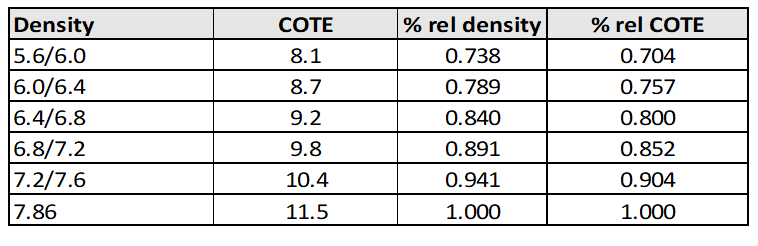
You can develop a linear equation for COTE as follows:
COTE (of a PM part) = relative density x (11.5 x 10⁻⁶)
The units of COTE are inches / inch °F, meaning that for every 1° F increase in temperature, the part will grow according to: length x COTE x change in temperature. The significance of this is that PM parts are going to grow with increasing temperature, which is crucial for the designer to understand. However, what may be more critical is how you would design an assembly of two parts to make sure you have optimal bond integrity between them.
Temperature
The COTE of wrought steel cannot be expressed as a single value; rather, the COTE of steel is temperature dependent.
From room temperature to 212°F, the COTE might be 12 x 10-6 inches / inch °F. However, at 1652°F, the COTE might be as high as 24 x 10-6 inches / inch °F.
The rationale for this is that you have the ferrite-to-austenite phase transformation, which can result in a large jump in COTE. Austenitic stainless steels are assumed to have a constant COTE as the temperature increases.
Dimensional Change
The final factor for COTE is the dimensional change of the metal powder. There are two ways to present dimensional change of powder metal parts during sintering.
The traditional method is the dimensional change from die size, which also includes the green-to-sintered dimensional change. This is most convenient for traditional part production.
However, when sintering bonding two distinct materials, it’s necessary to consider the green-to-sintered part size, or pre-sintered part size. The rationale for this? The two parts to be sinter bonded are in either the green or pre-sintered condition, and this is the critical dimension that establishes the initial gap of the two components.
Configuring Materials for Optimal Sinter Bonding
While it might not seem like a big deal, the placement of materials determines the success of sinter bonding. In some of the trials done at Horizon Technology, we’ve tested sinter bonding with stainless steel and FY-4500 in the following configurations:
- Stainless steel on the outside and FY-4500 on the inside
- FY-4500 on the outside and stainless steel on the inside
In the first configuration, prior to sintering the gap between the two materials was identified to be 0.002”. While considering both temperature and dimensional change, we found that between 932°F and 1670°F, the gap decreased significantly. However, between 1670°F and 1832°F, the gap actually increased, preventing adequate sinter bonding.
Reversing the location of the stainless steel and the FY-4500 will impact the relative gaps both at temperature without the influence of dimensional change and with the influence of dimensional change. This proves that having the FY-4500 on the outside and the stainless steel on the inside increases the likelihood of successful sinter bonding.
But we’re not out of the woods yet.
Solutions for Sinter Bonding Challenges
What all of this data shows is that regardless of the assembly configuration (stainless outside or inside), the gap at sintering temperature is too large for sinter bonding to take place.
This large gap occurs because both stainless and the FY-4500 shrink at sintering temperature. The dual shrinkage will cause the gap to only increase, making sinter bonding difficult. You can overcome this by fully sintering the stainless steel part and then sinter bonding, but there are additional costs associated with this.
When it becomes obvious that sinter bonding won’t create a sufficiently reliable bond between parts, how do we accomplish this?
Enter Sinter Brazing
Unlike sinter bonding where nothing is required between the parts, sinter brazing requires the introduction of a third element, hence the brazing material.
While sinter brazing might be a good way to cure your sinter bonding troubles, it comes at an additional cost. Adding more material and labor to the process will mean an increase in price.
Assembling the parts to be brazed requires more skilled labor to make sure the configuration is stable, and won’t impact the integrity of the finished bond.
For many people, the immediate choice is sinter brazing because it is:
- A tried-and-true method
- Relatively material independent
- Well accepted by the end users
However there are other ways of getting the perfect bond for your parts. A good example would be sinter bonding as long as the configuration provides the right combination of COTE and dimensional change for a good bond.
Optimizing Your Solution: PM Part Sinter Bonding or Sinter Brazing
Sinter bonding can be an intensive process, so knowing what’s what will either make or break your assembly. Sinter brazing, too, takes a skilled hand and the right temperatures. Partnering with a PM supplier that’s skilled in both sinter bonding and brazing will elevate your PM part’s performance.
To learn more about what’s possible beyond the “safe” and “easy” with advanced powder metal technology, take a look at our capabilities guide!