Looking for the right material and process for your metal project? You can learn a great deal about the properties of a ferromagnetic material by studying its magnetic hysteresis loop. You can also learn how to minimize losses in DC machines (and maybe even ACs too!).
A hysteresis loop shows the relationship between the induced magnetic flux density (B) and the magnetizing force (H). That’s where the infamous BH curve comes from. We’ll explain the alphabet soup in greater detail in a minute.
If you’re totally familiar with electromagnetic materials, forget this article. But if you’re curious about how a magnetic hysteresis loop applies to powder metal and your project, read on.
Hysteresis Loss in DC Motors: The Magnetic Domain Theory
Prior to discussing a typical BH curve, it’s worth briefly covering the magnetic domain theory. It’ll be quick -- promise!
Magnetic domains are similar to the grain structure of all metals, just smaller. Think of them as mini-magnets within a material.
Domains are randomly oriented within a non-magnetized ferromagnetic material, which effectively cancels any net magnetic moment.
A fully magnetically saturated material will have all domains aligned in one direction (let’s say to the top of this page). A fully demagnetized material will have various domains randomly oriented in the two dimensions of the page, canceling each other. Obviously, magnetism is a 3D phenomenon, but the same analogy can still apply.
How Does This Relate to the BH Magnetization Curve?
The BH curve (basically another way of saying the hysteresis loop) represents the necessary applied field (x-axis) required to achieve a certain level of magnetic induction (y-axis). In terms of the domain theory, the microscopic domains are reorienting in the direction of the applied field, thus overcoming some of their random orientation.
When enough field is applied, all domains will be oriented in one direction and the metal will reach magnetic saturation. Further increases in applied field will not alter the domain orientation.
So, magnetism is not any large-scale change in the material but rather a musical chairs of microscopic magnetic domains.
Hysteresis Loss in DC Motors Chart
The chart below is representative of most ferromagnetic materials (fully demagnetized or magnetically annealed before testing).
This shows a current inducing a magnetic flux on the sample material. With increasing current, the induced magnetic flux also increases. At the normal levels of applied field, when the field is reduced to zero, there is some residual magnetism remaining in the sample. It requires a certain level of current in the opposite direction to effectively demagnetize the material.
This lack of reversibility is called hysteresis; it actually implies some energy loss during the magnetize-demagnetize cycle. This is why the initial magnetization curve is not retraced when the applied current is reduced to zero. Hysteresis is constant, and constant losses in DC machines are a formula for inefficiency.
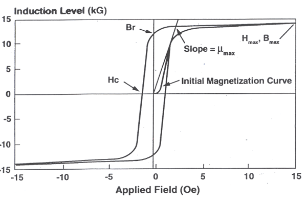
So what are the factors on which hysteresis loss depends? Let’s start by breaking down each element of this chart showing a BH curve of magnetic material:
● µmax -- the slope of the initial magnetization curve is referred to as “µ,” or the permeability of the material. Often a material is characterized by the maximum permeability, µmax. This is simply the instantaneous maximum slope of the magnetization curve.
● Br -- the residual magnetism for the given conditions when the applied field is turned off. Relative to the domains we talked about earlier, this represents how many domains remain reoriented as a result of the applied field.
● Hmax -- magnetic force (measured in oersteds). This measures maximum magnetic intensity applied within a metal.
● Bmax -- magnetic flux density (measured in kilogauss). This is defined as the amount of magnetic flux in an area taken perpendicular to the flux's direction.
● Induction level -- the level to which a material is magnetized by an external field. Measured in gauss, kilogauss, or tesla.
● Hc -- the coercive force of a material. If you have a material that wants to be reversed from plus to zero, this is the amount of energy you have to put in to reverse it. The lower the number, the less energy you have to consume.
● Applied field -- how much current (aka energy) do you have to put in to get a certain voltage? Measured in oersteds.
● Visa bar -- a perfect material would be infinitely up and infinitely down on this chart, with no broadening. That’s physically impossible, so this bar is a measure of how good the material is.
Note the BH curve has a mirror-like appearance above and below the x-axis. This means the direction of the current does not alter magnetic behavior.
H (in Oersted) = (Current in amps x 1.777 x Number of secondary turns) / magnetic path length
Although the curve above is for DC magnetic testing; it can also be used to evaluate AC applications, such as hysteresis loss in induction motor materials. In many cases the AC curve will begin to distort relative to the DC BH curve. This distortion is a result of the eddy currents generated with the test material.
Staying in the Hysteresis Loop
The hysteresis loop shows that magnetization is easier for materials that contain large particles.
More specifically and more importantly, for a material to be soft magnetic, its hysteresis loop should be as thin and high as possible. For your material, this translates to:
- Low coercive force
- High magnetic permeability
- High saturation induction value
Since hard magnetic materials are difficult to demagnetize, their external magnetic field will last indefinitely (at least until an external source demagnetizes them). For this reason, they are used in applications where permanent magnetization is a must:
- Memory devices
- Speakers
- Sensors
- Magnetic recording
For soft magnets, their ability to easily magnetize and demagnetize makes them ideal candidates for both AC and DC applications. The “BH” curve above is a method to evaluate the magnetic performance of materials in both the DC and AC conditions. It’s useful because it quickly shows magnetic performance of a material and can be readily used to compare it to others.
Soft magnetic materials see wide use as cores in transformers and inductors to enhance and/or channel the produced magnetic flux. The dissipation of energy in a magnetic core during its magnetization and demagnetization cycle is called core loss. These losses are not a big issue for hard magnets, but they’re crucial to the efficiency of soft magnetic applications -- and can becontrolled with proper materialselection. Imagine having acute control over stator core loss!
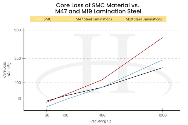
The data shown for M47 and M19 are based off of a single lamination. However, most motor stators aren't made of single sheets. Read more to learn about single sheet laminations compare to laminated assemblies .
Hysteresis Loss
Core losses are generally divided into three types:
- Hysteresis losses
- Eddy current losses
- Wire losses
Hysteresis losses originate from the movement of the domain walls back and forth under a magnetization-demagnetization loop. The presence of impurities, imperfections, and other features in a metal block can increase these losses. They exhibit a linear relationship with the frequency of the applied field.
Eddy current losses are losses generated during AC applications of ferromagnetic materials. Think of them as the resistance of the material to the changing magnetic fields. Specifically, the eddy currents oppose the alternating current and generate heat with the ferromagnetic material. These losses can become significant as you up the operating frequency.
Wire losses are, as the name implies, inefficiencies generated by the heating of the copper wire. Energy is consumed during this heating. One way to think about this loss is how a household extension cord gets hot when it’s been on a long time. Unlike the extension cord, though, copper losses in AC devices are factored into the design.
Soft Magnetic Motor Material Benefits
Now, how to minimize or reduce hysteresis loss? Powder metallurgy has attracted the interest of engineers and purchasers looking to develop new and advanced electromagnetic products for both AC and DC applications. DC applications are best served by sintered soft magnetic materials. AC applications are best realized by using soft magnetic composites.
Either way, powder metallurgy is coming into its own because of its low production costs, minimal material waste, and ease of recycling. The expanding interest in iron-based composites in electrical devices, such as motors, is in part thanks to a variety of impressive properties.
SMCs own several advantages over laminated steel sheets, for example:
- Easy shape-making (both AC and DC applications)
- Excellent solution for how to reduce eddy current loss (AC/SMC applications)
- High magnetic permeability (DC/sintered magnetic applications)
- Higher resistivity (AC/SMC applications)
BH Magnetization Curve: Powder Metal Vs. Electrical Steel
Look at the differences in the BH curves of electrical steel laminations and soft magnetic composites (SMCs):
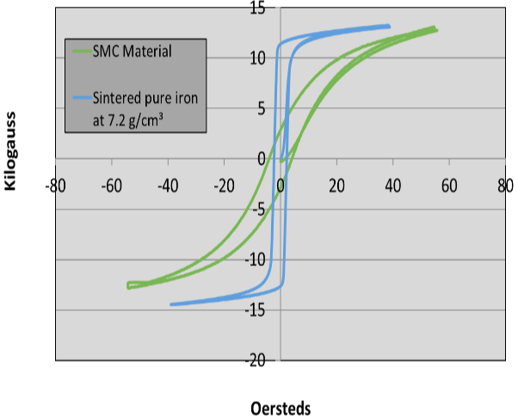
In the chart above, the lamination steel is actually a sintered pure iron material compacted to a density of 7.2 g/cm³. The takeaway is that the magnetic composite material has a lower permeability and requires more current to achieve the same induction level; a definite disadvantage for SMCs.
This is why you hear the criticism that SMCs have a higher hysteresis loss relative to steel laminations. Hysteresis losses are assumed to generate heat to the first power of the frequency.
But hysteresis losses are only one component of the total losses in AC devices. A second, and often more impactful, loss is the so-called eddy current loss. These are the result of the applied alternating current inducing circulating currents within the ferromagnetic material.
Eddy current losses are assumed to generate heat proportional to the frequency of operation raised to the second power. That means eddy current losses are often more dominant at higher frequencies.
(Note: One magnetic quality not mentioned above? Saturation induction, or the max flux a material can store. This is a function of density. Processing will not alter this characteristic.)
Comparing BH Magnetization Curves by Frequency
Fairly recent experimental work has looked at the hysteresis curve for an SMC material at varying frequencies. The goal? To see how the BH curve changed shape with the varying frequencies. The following chart shows how the BH curves compare at different frequencies:
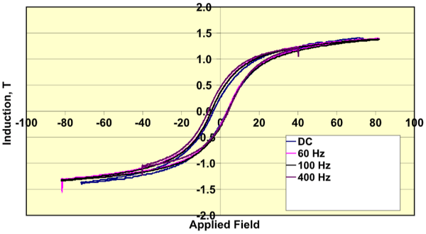 What we think this chart is showing is that for soft magnetic powder materials, the shape and relative position of the BH for each frequency remains almost exactly on top of each other. This implies that the main losses for SMCs at the frequencies tested are almost exclusively hysteresis losses.
Yes, it is impossible to totally eliminate all eddy current losses, but these are a minor contribution in SMCs up to their intended design
limit. This is why SMC are superior to laminate steel in high-frequency applications.
Now, let’s think about how you could improve the various magnetic properties represented by the BH curve -- and therefore improve your product’s performance:
Component Permeability
You can improve component permeability by
- Increasing density
- Alloying the iron with phosphorus or silicon
- Minimizing any carbon or nitrogen pickup during sintering
- Improving the purity of the iron
- Minimizing any subsequent processing of the part (sizing, machining, etc.)
Some of these qualities apply to both soft magnetic composite and sintered soft magnetics. If the part does require secondary processing, the part can be annealed to avoid associated adverse effects.
Maximum Induction of Material
You can improve maximum induction by:
- Increasing part density
- Improving the purity of the iron material
- Minimizing any subsequent processing
Residual Magnetism
Residual magnetism (hr) can be improved by the same factors that improve the permeability. Also called remanence, it can be used to provide the magnetic memory in magnetic storage devices.
Coercive Force
You can lower coercive force by:
- Alloying with phosphorus or silicon
- Minimizing any carbon or nitrogen pickup during sintering
- Minimizing any subsequent processing
Want to Go More In-Depth on Soft Magnetic Materials?
The qualities of soft magnetic composites and whether they fit your design needs are highly reflected in the hysteresis loop.
If you need more help understanding how magnetism and material choice impacts your product’s performance, get in touch with us.
If you or your engineering team want to do more research on magnetism and materials, try these additional materials on magnetism and powder metals’ relationship, plus our free visual guide to SMCs and motor efficiency.
- What is Soft Magnetic Composite?
- ASTM A314/A 341M -- Test method for DC Magnetic Properties of Materials
- ASTM A 811 -- Specification for Soft Magnetic Iron Parts Fabricated by PM Techniques
- ASTM A 712 -- Test Method for Electrical Resistivity of Soft Magnetic Materials
- MPIF Standard 35
- “Ferromagnetism” by Richard M. Bozorth
- “Soft Magnetism, Fundamentals for Powder Metallurgy and Metal Injection Molding”, Chaman Lall.

(Editor's note: This article was originally published in November 2018 and was recently updated.)