As an engineer tasked with bringing your product into the future, you probably have many decisions to make when choosing the motor design of your AC project.
The most common applications of electrical motors fall into two main categories -- axial flux motors vs. radial flux motors. There’s also a third category -- transverse flux motors -- but this configuration is not as widespread (yet).
For decades, radial flux motors were the most common solution. However, for reasons we’ll discuss below, axial flux machines are becoming the standard for AC motor performance.
Because of the limitations of traditional laminated steel stacks, we’ll also examine how powder metallurgy helps unleash new opportunities for all three designs.
What's the Difference Between Axial, Radial, & Transverse Electric Motor Design?
While all three types can be created as permanent magnet synchronous motors, the fundamental differences lie in the orientation of the magnetic field to the electric coils.
Radial Flux Motor
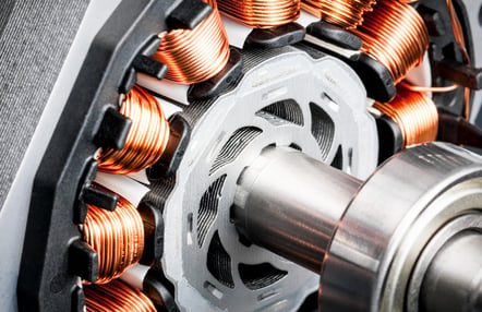
In short, features of a radial flux permanent magnet motor are designed on the sides. The copper windings are wrapped around slots. The flux is generated perpendicular to the axis of rotation.
As an example, traditional radial flux BLDC motors consist of a rotor made of permanent magnets located inside a stator. In this case:
- A stator contains support known as a yoke, which is outfitted with "teeth" containing electromagnetic coils
- The teeth function as alternating magnetic poles
- The rotor’s magnetic poles interact with the alternating magnetic flux of the wound stator teeth, resulting in the motor’s torque
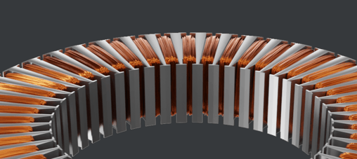
Axial Flux Motor:
An axial flux BLDC motor design has a different geometry from a radial machine.
In this case, the flux is generated parallel to the axis of rotation because of the way it’s wound. This carries the advantage of simplifying fabrication of the motor.
Although this type of electric motor geometry is far from new, it was rarely used in commercial applications due to manufacturability and costs when using laminations. Soft magnetic composite (SMC) materials exclusive to powder metal are are allowing designers to exploit the axial topology’s advantages, driving the future of axial flux motors:
- High power density (More on this in a bit)
- Simplified high-current BLDC motor winding design
- Shorter magnetic path
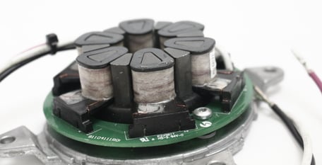
Transverse Flux Motor:
Transverse flux motors (TFM motors) take a different motor stator winding design approach.
Instead of winding copper wire around the stator teeth or the pole, the TFM has coils circumferentially around the axis of rotation.
 (Photo courtesy Linear Labs)
This setup enables the 3D flow of magnetic flux, where it crosses axially through the stator, circumferentially through the rotor, and radially through the gap between them.
As a result, you can increase low-speed torque and efficiency or even increase the power for particular energy inputs and motor sizes. The TFM design is uniquely suited for SMCs, and with their lower inherent core losses, there’s decreased cooling requirements for this style motor.
How Do These Electric Motor Designs Differ in Performance?
Although the radial design has been the standard for decades, there are distinct features and performance advantages that axial and TFM motors offer. Today, they’re the preferred choice for modernizing your automotive or industrial application.
For example, think of a motor for a wheel hub -- what do you want it to do, first and foremost? Produce lots of torque. Because the axial and transverse motor designs can have the rotating member located on their outer diameter, they create higher torque while reducing their motor footprint.
An axial flux motor also has a higher power density, developing 30-40% more torque than a similar-sized radial motor, and has better cooling.
In a radial flux motor, magnetic flux moves from one tooth to the stator, back to the next tooth, and then to the magnets. On the other hand, an axial flux motor has a more efficient magnetic flux path: from one magnet, through the core, to another magnet.
Where Does Powder Metallurgy Fit Into the Conversation?
Every engineer agrees that permanent magnets increase motor performance. Today, how can we improve the manufacturing process to take that performance even further?
Traditional lamination is still the most common method for manufacturing rotors and stators. That process could include:
- Stamping
- Joining and assembly
- Riveting
- Welding
- Gluing
- Welding and subsequent machining or progressive stamping of the axial poles (in current axial flux lamination designs)
These lamination-specific processes deform the material's interior structure, weakening its magnetic properties. On the other hand, powder metallurgy’s 3D flux path and net shape-manufacturing capabilities eliminate secondary machining and joining. This breakthrough has given rise to the widespread use of ferromagnetic materials like soft magnetic composites.
SMCs consist of iron powder particles that are coated with a layer of electrical insulation. Because they can be produced into complex shapes through powder metallurgy, SMCs allow for 3D magnetic circuits and reduced core losses.
Soft magnetic composite materials can outperform electrical steel laminations at frequencies as low as 100 Hz, making them ideal for modernizing your high-frequency application, regardless of motor configuration.
New motor topologies are becoming a reality through the use of SMC materials.
SMC: The Perfect Solution for Electric Motor Design?
With a trend toward electrification, alongside calls for low-cost, high-efficiency motors, there’s surging demand for more efficient electromagnetic components. “Efficiency” must come from both cost and energy perspectives.
Core benefits of using soft magnetic composite materials in axial flux motor designs:
-
Sustainability: SMCs are 15% more energy efficient to produce over laminate steel, while improving recyclability and reducing dependence on copper and rare earth magnets.
-
High Performance: SMCs offer compact designs and high torque density using high iron copper loading.
-
Efficiency: SMCs reduce eddy current losses and cooling requirements of electric motors.
-
Reduced Cost: Compact motor designs result in less material, a simplified production process, and minimum waste.
For more resources on how to design a more efficient, compact, and high-torque electric motor, visit our Engineers' Hub.
Note: This article was originally published on June 30, 2021 and was updated on November 10, 2022.